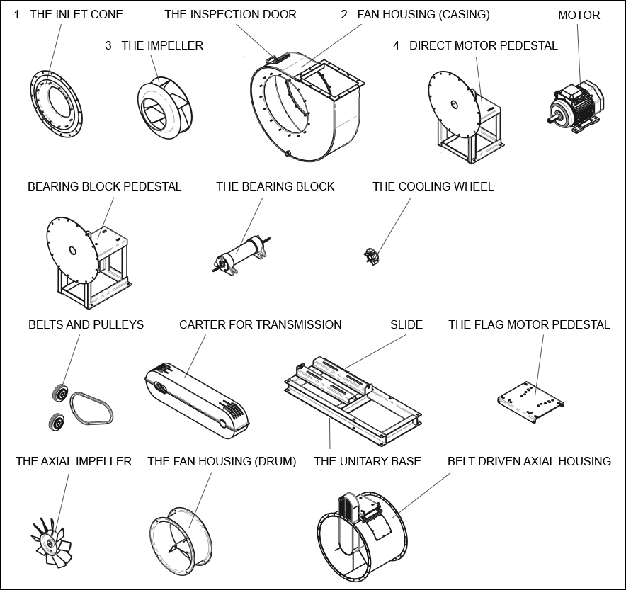
Id Fan Drawing
An industrial ID fan is a crucial component in various processes like power generation and manufacturing. Typically large and robust, it’s designed to handle high volumes of air or gas at low pressures. The fan consists of a sturdy housing that encases the impeller, which is the rotating part with blades. These blades are meticulously engineered to maximize airflow efficiency while minimizing noise and vibration.
The impeller is driven by a powerful motor connected via a shaft, ensuring smooth and reliable operation. The housing often includes features like inlet and outlet dampers or diffusers to control airflow and optimize performance. ID fans are tailored to specific applications, with variations in size, materials, and configurations to suit diverse industrial needs. Their primary function is to exhaust gases or fumes from a system, maintaining safe operating conditions and enhancing overall efficiency in industrial processes.
Specifications of ID Fans Drawing:
Component Identification: An ID fan will be represented as a distinct component in a process flow diagram or a mechanical drawing. It’s often labeled clearly as “ID Fan” or “Induced Draft Fan.”
Symbol: In process flow diagrams (PFDs) or piping and instrumentation diagrams (P&IDs), an ID fan is symbolized by a circle with a fan blade symbol inside it. The circle represents the fan housing, and the blades inside denote the impeller.
Orientation: The orientation of the ID fan in the drawing indicates its placement relative to other components such as the furnace, boiler, or stack. Typically, the direction of airflow (from the equipment into the fan) is indicated by an arrow.
Connections: The drawing will show inlet and outlet connections for the fan, often with labels indicating which side connects to the process equipment and which side leads to the stack or exhaust system.
Dimensions and Specifications: Depending on the level of detail, the drawing might include dimensions of the fan, its power rating, airflow capacity, and other specifications relevant to its operation.
Control and Instrumentation: In more detailed drawings (like P&IDs), control valves, dampers, and instrumentation related to the ID fan’s operation may be depicted, showing how it interfaces with the overall process control system.


